
ELV cable calculation: the method, the formula and a worked example
How to turn a floor plan into metres of cable and boxes to order: every term in the formula, which numbers are standards and which are habits, a worked metric example, and where fire alarm loops and PA lines need a different calculation.
- Doc no
- TQ-BLG-261014-TN
- Rev
- Issued
- Author
- Zakaria Syed
- Category
- Cabling
- Reading
- 8 min
ELV cable calculation for structured cabling and CCTV comes down to one formula per run: the rectilinear route from the rack to the device, measured on the plan and scaled, multiplied by a routing factor for the way containment really runs, plus the vertical drop to the device, plus slack at each end. Check every run against the 90 m permanent link, total the runs, add a waste allowance, and convert to boxes by how many whole runs fit in each box. The only hard numbers are the standards' length limits; slack and waste are project assumptions and should be written down as such.
run (m) = route on plan (m) x routing factor + vertical drop + device-end slack + rack-end slack
This is the cable step of the ELV quantity take-off guide; the worked ELV BOQ example uses its results.
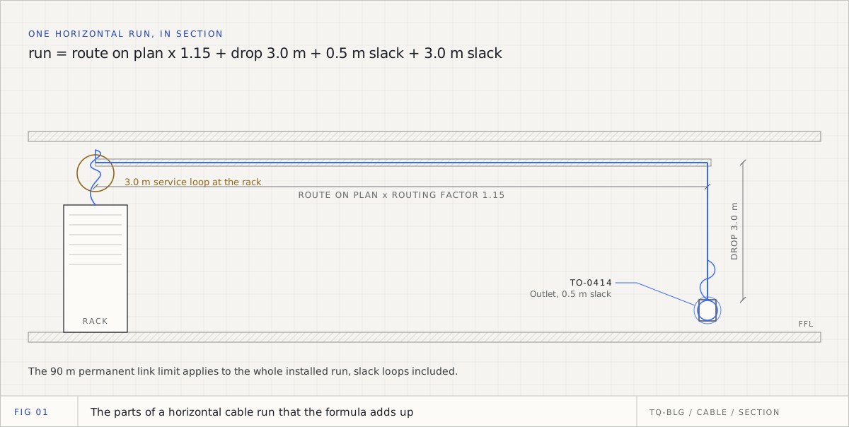
The inputs, and where each comes from
| Term | What it is | Where it comes from | Typical value |
|---|---|---|---|
| Route on plan | Distance from the rack to the device along the grid (x plus y, not the diagonal) | The plan, at the stated scale | Measured per run |
| Routing factor | Allowance for containment that bends around cores, beams and services | Your judgement, or the project's | 1.10 to 1.20 |
| Vertical drop | From the containment level down to the outlet, or up to a ceiling device | Ceiling void and outlet heights | 2.5 to 3.5 m for floor-level outlets |
| Device-end slack | Service loop at the outlet or device | Project specification | 0.3 to 0.5 m |
| Rack-end slack | Service loop in the telecom room | Project specification | 3 to 6 m |
| Waste | Offcuts, damage, re-terminations | Trade practice, not a standard | 7 to 10 percent |
Use the rectilinear distance because containment runs along the building grid, not across it. The routing factor then covers what the grid misses. A factor of 1.15 means a 40 m grid route is priced as 46 m of containment route.
What the standards fix, and what they leave to you
The standards set lengths, not quantities:
- 90 m permanent link. The fixed horizontal cable from the patch panel to the outlet. Fluke Networks: "The maximum permitted length of the permanent link is 90 meters."
- 100 m channel. The permanent link plus all the cords: "the overall 100-meter length of the channel includes both the fixed portion (i.e., 90-meter permanent link) and the equipment cords (a combined length of 10 meters)."
- ISO/IEC 11801 says the same. Telegaertner summarises it as a 100 m channel of 90 m horizontal cable and 10 m of cords in total. Longer cords mean a shorter allowed horizontal run.
- Solid for horizontal, stranded for cords. Stranded cable is limited to patch cords and 10 m within the 100 m channel.
- The current standard. ANSI/TIA-568.2-E, published in October 2024, replaced 568.2-D. Its power delivery annex recommends Category 6A or better where PoE is planned.
Two consequences for estimating. First, slack is installed cable, so it counts towards the 90 m: a run that is 88 m on the plan plus 3.5 m of slack is over the limit. Second, a field tester's length reading is not an order quantity. Testers apply a tolerance for the cable's nominal velocity of propagation, which is why a link can pass on length while being physically longer than 90 m. Estimate from the geometry of the route. What a tester will tolerate is a separate question.
Slack and waste are where the sources run out. An older edition of the BICSI TDMM, quoted in Cabling Installation & Maintenance in 1998, gave 3 m of slack at the telecom room and 30 cm at a twisted-pair outlet. Owner specifications today vary: one US university specification asks for at least 6 m in telecom rooms for all cable types. For waste, no standards body publishes a percentage. A cable manufacturer's estimating guide recommends adding a minimum of 7 to 10 percent and more as uncertainty rises. That is trade practice, and it should be labelled as such in your take-off.
Worked example: one office floor
Everything below is illustrative. The assumptions, stated once:
| Assumption | Value |
|---|---|
| Plan scale | 1:100 at A1, stated in the title block |
| Rack position | Riser room at the core, shown on the plan |
| Routing factor | 1.15 |
| Vertical drop | 3.0 m (containment at about 3.3 m, outlet at 0.3 m) |
| Device-end slack | 0.5 m |
| Rack-end slack | 3.0 m |
| Waste | 10 percent |
| Box size | 305 m |
Step 1: measure sample runs
Measure the rectilinear route to a spread of outlets: the nearest, the farthest, and a few in between.
| Outlet | Route on plan (x + y) | x 1.15 | + drop + slack (6.5 m) | Run | Under 90 m? |
|---|---|---|---|---|---|
| O-01 | 8 + 6 = 14 m | 16.1 m | 6.5 m | 22.6 m | Yes |
| O-02 | 18 + 9 = 27 m | 31.1 m | 6.5 m | 37.6 m | Yes |
| O-03 | 25 + 12 = 37 m | 42.6 m | 6.5 m | 49.1 m | Yes |
| O-04 | 32 + 4 = 36 m | 41.4 m | 6.5 m | 47.9 m | Yes |
| O-05 | 40 + 14 = 54 m | 62.1 m | 6.5 m | 68.6 m | Yes |
| O-06 | 46 + 18 = 64 m | 73.6 m | 6.5 m | 80.1 m | Yes |
| O-07 | 72 + 20 = 92 m | 105.8 m | 6.5 m | 112.3 m | No |
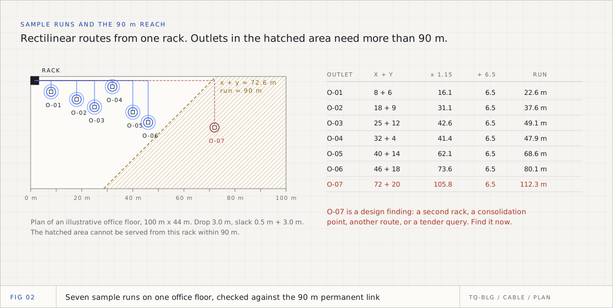
O-07 is over the limit. That is a design finding, not an estimating detail: it needs a second rack, a consolidation point, a different route, or a query to the consultant. Find it at take-off, not at testing.
Step 2: extend to the floor
The floor has 96 data points. With the far wing (O-07 and its neighbours) moved to a second rack by the designer's response, the remaining runs on this rack span 22.6 m to 80.1 m. Two ways to total them:
- Measured runs. Measure every run. Most accurate; slow by hand.
- Floor average. The common estimating shortcut: average run = (longest + shortest) / 2 = (80.1 + 22.6) / 2 = 51.4 m. It assumes outlets are spread evenly between the nearest and the farthest, which is reasonable on an open office floor and poor on a floor where most outlets cluster at one end.
By average: 96 x 51.4 m = 4,934 m, plus 10 percent waste = 5,428 m.
Whichever you use, say which. A cable schedule that mixes measured and averaged runs without labelling them looks more precise than it is. In TrueQty every cable schedule row shows its own arithmetic and is labelled as measured or estimated by average, so a reviewer can tell at a glance which numbers rest on a real route.
Step 3: convert to boxes
Most cable quantities go wrong at this step.
| Method | Calculation | Boxes |
|---|---|---|
| Total length / 305 | 5,428 / 305 = 17.8 | 18 |
| Whole runs per box | 305 / 51.4 = 5.9, so 5 runs per box; 96 / 5 = 19.2 | 20 |
A horizontal run cannot be spliced from two boxes, so the second method is the one that matches what an installer will open. Notice that it already absorbs most of the waste allowance: 20 boxes is 6,100 m against 4,934 m of runs, a margin of 24 percent made of box remnants. Our practice: calculate both, order the larger, and state which governed. Adding a waste percentage on top of the runs-per-box figure usually double counts.
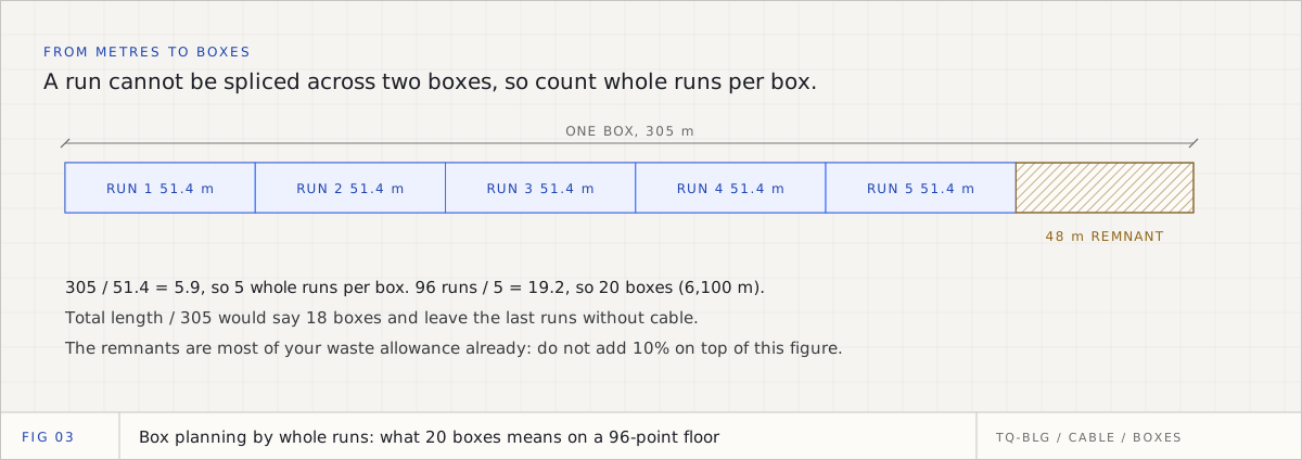
Backbone and risers
Backbone links (fibre or multi-pair copper from each floor rack to the main equipment room) are calculated per link, not averaged:
link (m) = horizontal distance to the riser + floor-to-floor height x floors + slack at each end
With 4 m floor-to-floor, 20 m of horizontal route and 5 m of slack at each end, a link from level 6 is 20 + 24 + 10 = 54 m. TrueQty's defaults for this are a 4 m floor height on commercial buildings (3 m residential, 8 m warehouse), 5 m of backbone slack at each end and a 90 m maximum horizontal run, all editable per project, and any run over 90 m is flagged rather than silently priced. Read link counts and cable types from the riser schematic, not from the floor plans.
CCTV, fire alarm and PA are different calculations
CCTV uses the same twisted-pair method: one run per camera, the same 90 m permanent link and 100 m channel. PoE does not extend the distance; it adds a power budget (see the BOQ example) and, under TIA-568.2-E's power delivery annex, a recommendation for Category 6A or better. External cameras on poles add the pole height and the underground route to the pole.
Fire alarm is a loop, not a star. The UAE Fire and Life Safety Code requires Class A wiring, and all fire detection and alarm wiring to be 2-hour fire rated and Civil Defence listed. Class A means the loop leaves the panel, passes every device and comes back to the panel on a separate path, so you price the whole loop, out and back, and not the one-way distance to the farthest device. On a long floor the return leg alone can be as long as the route out. The length limit comes from the panel manufacturer rather than a cabling standard. One common loop module allows up to 3,810 m on a Class B loop. Run the manufacturer's loop calculation, and remember that conductor resistance rises in a fire: one cable manufacturer's example shows voltage drop rising from 1.4 percent to about 4.3 percent at fire temperature, enough to need a larger conductor.
Public address and voice alarm use 100 V line distribution. A higher line voltage carries the same power at lower current, which allows thinner cable over longer distances, so cable is sized by power and acceptable loss per zone, not by a 90 m rule. In the UAE, voice evacuation cabling must also be 2-hour fire rated.
The checklist
- Scale confirmed from the title block, never assumed.
- Rack positions known; if not, every length is an estimate and labelled as one.
- Routing factor, drop, slack and waste written down as assumptions.
- Every run checked against 90 m, slack included.
- Boxes calculated by whole runs per box.
- Backbone calculated per link from the riser schematic.
- Fire alarm and PA calculated as loops and lines, with the manufacturer's tools.
For how cable quantities feed the bill, see the ELV BOQ worked example; for tools that calculate cable at all, the 2026 take-off software comparison. TrueQty's cable schedule uses the same formula and shows it on every row.
Take off one real ELV sheet, with the evidence for every count on the drawing.
14 days, one full ELV tender, no card. Sign up with your work or personal email. You check every count, a team lead approves each sheet, and only approved sheets reach the BOQ.
Questions engineers ask
- Q01What is the maximum length of a Cat6 horizontal run?
- The permanent link, from the patch panel to the outlet, is limited to 90 m, within a 100 m channel that allows a combined 10 m of patch and equipment cords. The same limits appear in TIA-568 and ISO/IEC 11801. Slack loops are part of the installed cable, so they count towards the 90 m.
- Q02How much slack should I allow at the rack and at the outlet?
- There is no single number. An older BICSI TDMM edition quoted 3 m at the telecommunications room and 30 cm at the outlet for twisted pair; owner specifications range from about 1 m to 6 m at the room. Use the project specification if it states one, and record your value as an assumption if it does not.
- Q03What waste percentage should I add to cable quantities?
- No standards body publishes one. Trade practice is to add 7 to 10 percent, more when routes are uncertain. If you convert to boxes by whole runs per box, the box remnants already cover much of that allowance, so compare the two methods and state which one you used.
- Q04How do I convert metres of cable to 305 m boxes?
- Divide 305 by your average run length and round down to get whole runs per box, then divide the number of runs by that and round up. Dividing total metres by 305 understates the order, because a horizontal run cannot be spliced from two boxes.
- Q05Does PoE change the maximum cable length?
- No. PoE runs over the same twisted-pair channel, so the same 100 m channel and 90 m permanent link apply. It does change the cable choice and the power budget: the current TIA twisted-pair standard recommends Category 6A or better for power delivery, and switches should be sized on each device's maximum draw.
Sources
Every external fact in this document is cited to one of these, fetched when it was written.
- [01]Fluke Networks, Channel, Permanent Link, Patch Cords, MPTL, E2Eflukenetworks.com
- [02]Fluke Networks, Say Goodbye to the Weakest Linksflukenetworks.com
- [03]Fluke Networks, Stranded vs. Solid Wire Cable: How to Chooseflukenetworks.com
- [04]Fluke Networks, Going the Distance (length tolerance in testing)flukenetworks.com
- [05]Telegaertner, Longer Patch Cords Mean Shorter Horizontal Cable (ISO/IEC 11801 lengths)telegaertner.com
- [06]Siemon, ANSI/TIA-568.2-E Released (Annex H on power delivery)siemon.com
- [07]Cabling Installation & Maintenance, Service loops in horizontal cable runs (1998)cablinginstall.com
- [08]LSU Health Sciences Center, Specification 27 15 00 Communications Horizontal Cablinglsuhsc.edu
- [09]TrueCable, Cable Waste Math: How to Estimate Your Box Counttruecable.com
- [10]Honeywell, LCM-320 Loop Control Modulebuildings.honeywell.com
- [11]Dubai Civil Defence, UAE Fire and Life Safety Code of Practice (September 2018)dcd.gov.ae
- [12]Prysmian, Voltage drop during firetr.prysmian.com

Zakaria is a mechanical engineer and the co-founder and COO of AI Agentiva in Dubai. He builds TrueQty, and writes here about how ELV quantities are counted, checked and priced, and where take-offs go wrong.
Related documents
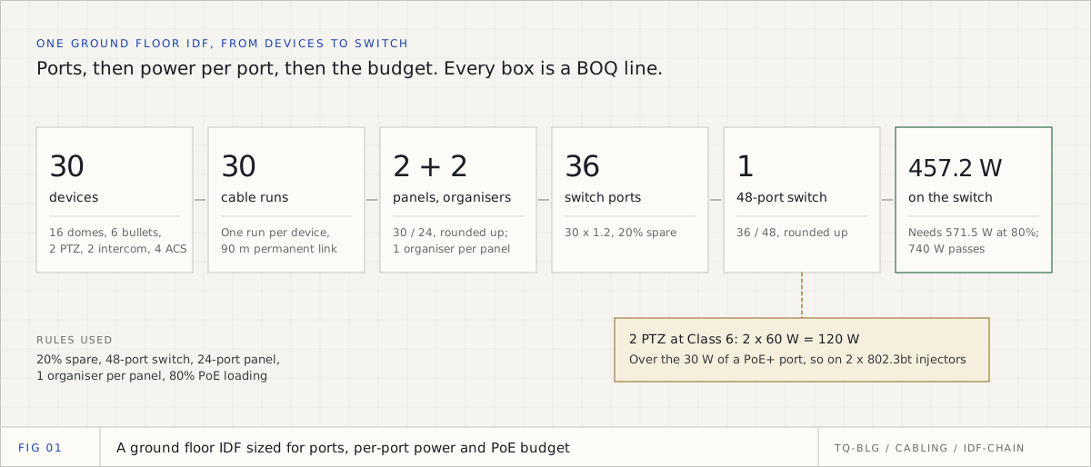
How many PoE switches for CCTV: the switch, PoE budget and patch panel calculation
Switches for a CCTV system are sized three times over: by ports, by the power each port must give, and by the power the whole switch can give. Then the patch panels, organisers and rack follow. One ground floor IDF, worked through with the IEEE numbers.
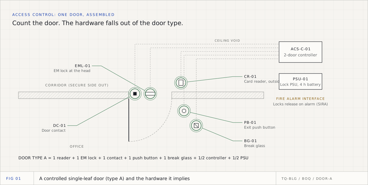
How to build an ELV BOQ from drawings: a worked example across CCTV, access control and structured cabling
A worked example that takes one illustrative office building from drawings to a bill of quantities across three systems, with the basis of every number written next to it and a sample BOQ table you can reuse.
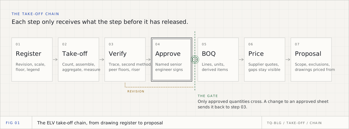
ELV quantity take-off: the complete guide for GCC pre-sales engineers
An ELV take-off is not one count. It is six kinds of reasoning across CCTV, access control, cabling, fire alarm, PA and intercom, checked before any number is priced. This is the whole process, written for the engineer who has to defend it.